圓線圖

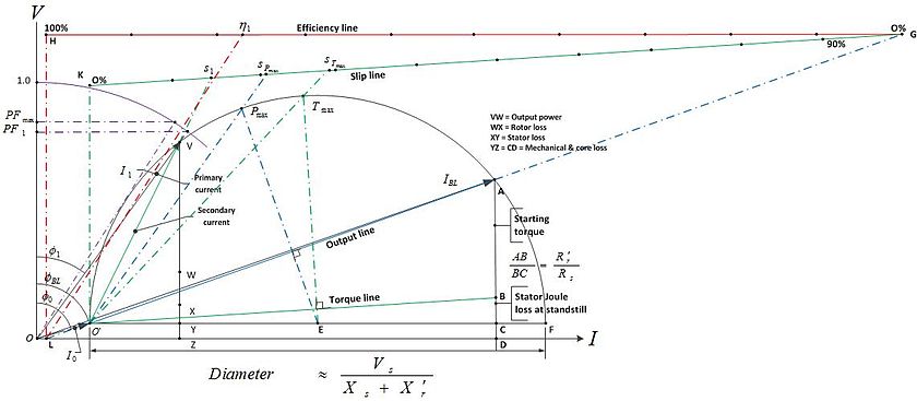
圓線圖(circle diagram)是由圖形方式表示电机性能的方式,最早是由A. Heyland及B.A. Behrend在1894年、1895提出[1][2][3]。是由電機輸入電壓及電流的軌跡來繪製[4]。圓線圖可以用來表示交流發電機、同步馬達、變壓器及感應馬達的性能。Heyland圖是圓線圖應用在感應馬達上的近似表示法,其中假設定子輸入電壓、轉子電阻及轉子電抗為定值,定子電阻及鐵損為零[3][5][6]。另一種常見的圓線圖是針對固定氣隙的感應馬達,描述如下[7][8] 其中
- Rs, Xs:定子電阻及定子漏電抗
- Rr', Xr', s:转子電阻及转子漏電抗、轉子滑差
- Rc, Xm,:鐵損及機械損,磁化電抗
- Vs:定子電壓
- I0 = OO', IBL = OA, I1 =OV:無載電流、堵轉電流,工作作電流
- Φ0, ΦBL:無載功因角,堵轉功因角
- Pmax, sPmax, PFmax, Tmax, sTmax:最大輸出功率及對應氣隙,最大功因、最大轉矩及對應氣隙
- η1, s1, PF1, Φ1,:工作電流下的效率、滑差、功因及功因角
- AB:表示轉子功率輸入,除以同步轉速後為啟動轉矩
圓線圖是根據開路測試以及變壓器的短路測試或是馬達堵轉測試所得,會得到一個符合O'和A點的半圓。
圓線圖因為假設氣隙為定值,因此會引入誤差,其他的誤差有因為磁飽和對轉子磁阻及電抗的影響,以及從無載到工作速度範圍之間的轉子速度變化,對轉子磁阻及電抗的影響

參考資料
[编辑]- ^ Behrend, B.A. The Induction Motor and Other Alternating Current Motors, their Theory and Principles of Design. McGraw-Hill. 1921: ix [4 January 2013]. (原始内容存档于2019-07-08).
- ^ Heyland, A. A Graphical Method for the Prediction of Power Transformers and Polyphase Motors) (PDF). ETZ: 561–564. 1894 [4 January 2013]. (原始内容存档 (PDF)于2020-03-20). 参数
|journal=与模板{{cite web}}不匹配(建议改用{{cite journal}}或|website=) (帮助);|volume=被忽略 (帮助) - ^ 3.0 3.1 Terman, Frederick Emmons; Freedman, Cecil Louis; Lenzen, Theodore Louis; Rogers, Kenneth Alfred. The General Circle Diagram of Electrical Machinery 49. American Institute of Electrical Engineers, Transactions of the. Jan 1930.
- ^ S.K.Bhattacharya. Electrical Machines 2008. Tata McGraw-Hill Education. : 359. ISBN 0-07-066921-X.
- ^ Heyland, Alexander. A Graphical Treatment of the Induction Motor. G.H. Rowe, R.E. Hellmund (trans.). McGraw Publishing Company. 1906 [10 January 2013].
- ^ Phase to Phase BV. The Asynchronous Motor Model (PDF): 5–6. 2006 [10 January 2013]. (原始内容 (PDF)存档于2014年8月10日).
- ^ Alger, Philip L.; et al. 'Induction Machines' subsec. of sec. 7 - Alternating-Current Generators and Motors. A.E. Knowlton (Ed.) (编). Standard Handbook for Electrical Engineers 8th. McGraw-Hill: 710–711. 1949.
- ^ Fernandez, Francis M. Construction of Circle Diagram (PDF). College of Engineering Trivandrum. [10 January 2013]. (原始内容 (PDF)存档于2014-08-08).